Home » Without Label » 555 Timer Schematic - Schematic Of Speaker With A 555 Timer With No Programming Needed / The 555 can be used as a schmitt trigger by shorting pins 2 (trigger) and 6 (threshold) together and applying the input signals directly to these points, as shown in the functional diagram and circuit in figure 1.
555 Timer Schematic - Schematic Of Speaker With A 555 Timer With No Programming Needed / The 555 can be used as a schmitt trigger by shorting pins 2 (trigger) and 6 (threshold) together and applying the input signals directly to these points, as shown in the functional diagram and circuit in figure 1.
555 Timer Schematic - Schematic Of Speaker With A 555 Timer With No Programming Needed / The 555 can be used as a schmitt trigger by shorting pins 2 (trigger) and 6 (threshold) together and applying the input signals directly to these points, as shown in the functional diagram and circuit in figure 1.. The 555 timer is a simple integrated circuit that can be used to make many different electronic circuits. The 555 can be used as a schmitt trigger by shorting pins 2 (trigger) and 6 (threshold) together and applying the input signals directly to these points, as shown in the functional diagram and circuit in figure 1. The block diagram of a 555 timer is shown in the above figure. 555 timer ics need dc voltage in order to operate. In this project, we are using 555 timer ic to create various timer circuit like 1 min timer circuit, 5 min timer circuit, 10 min timer circuit, and 15 min timer circuit.
In this circuit, we will connect the 555 timer to be in astable mode. To prevent 555 timer from flyback current in the relay use a diode before the relay. A monostable 555 timer is required to produce a time delay within a circuit. The output voltage from the chip is around 1.5 v lower than vcc when high and around 0 v when low. We have a large collection of simple and advanced projects using 555 timer ic.
555 Timer Ic Wikipedia from upload.wikimedia.org The above schematic shows the 555 timer bistable multivibrator circuit. Also, 555 timer is used to generate an oscillating pulse. The effect is quite dramatic. This is the pin which connects to the dc voltage to power the 555 chip. The voltage must be at least 4.5v and no greater than 15v. This pin connects to the negative side of the battery. The standard 555 timer ic is made of 2 diodes. In the inner configuration of this ic flip flop and comparator circuit are present which helps the circuit to behave like a toggle switch.
It's common to run 555 timer circuits using 4 aa or aaa batteries for 6v or a single 9v battery.
In 2017, it was said over a billion 555 timers are produced. Here is a simple and interesting hobby circuit that can be made using the popular 555 timer ic. To prevent 555 timer from flyback current in the relay use a diode before the relay. As the name indicates, only one state is stable and the other one is called unstable or quasi stable state. In this category, we have handpicked some really useful 555 timer circuits which will be interesting to electronics engineering students and hobbyists alike. 555 can be used as a delay device, a trigger, or a starting resonator element in a circuit. A monostable 555 timer is required to produce a time delay within a circuit. In this project, we are using 555 timer ic to create various timer circuit like 1 min timer circuit, 5 min timer circuit, 10 min timer circuit, and 15 min timer circuit. Because of their availability and ease of use, the 555 astable circuit is the common source of clock signal in many synchronous circuits. Resistive network consists of three equal resistors and acts as a voltage divider. 555 ic automatically switches back to. 555 timer ics need dc voltage in order to operate. 555 timer ic remains in stable state until the external triggering is applied.
We have a large collection of simple and advanced projects using 555 timer ic. Because of their availability and ease of use, the 555 astable circuit is the common source of clock signal in many synchronous circuits. An external triggering is required for transition from stable to unstable state. 555 timer was first introduced by signetics corporation in 1971 as se555/ne555. The 4rth circuit diagram shows the standard ic 555 adjustable timer circuit having two sets of timing ranges and an output relay for toggling the desired load.
555 Timer Tutorial And Circuits Build Electronic Circuits from www.build-electronic-circuits.com The 555 timer is a simple integrated circuit that can be used to make many different electronic circuits. If you want to know all the pinout of the 555 timer, what each pin is and what each pin does, see 555 timer pinout. 555 datasheet 555 duty cycle 555 metronome 555 reset function 555 time delay relay inverted 555 timer pulse generator. 555 ic timer block diagram 555 ic timer block diagram. The 4rth circuit diagram shows the standard ic 555 adjustable timer circuit having two sets of timing ranges and an output relay for toggling the desired load. As we know 555 timer ic is one of the commonly used ic among students and hobbyists. Rain alarm using 555 timer. 555 timer ic is an integrated circuit used in a variety of timer, pulse generation circuit, and oscillator circuit applications.
To understand the basic concept of the timer let' s first examine the timer in block form as in figure 1.
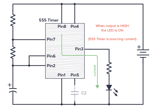
The standard 555 timer ic is made of 2 diodes. Here is the practical demonstration of the bistable mode of 555 timer ic, where we have connected a led to the output of the 555 ic. There are 24 different 555 timer circuits in this book! A monostable 555 timer is required to produce a time delay within a circuit. The 555 can be used as a schmitt trigger by shorting pins 2 (trigger) and 6 (threshold) together and applying the input signals directly to these points, as shown in the functional diagram and circuit in figure 1. 555 timer was first introduced by signetics corporation in 1971 as se555/ne555. There are simple circuits for beginners and advanced engineers. The 555 timer ic is an integrated circuit (chip) used in a variety of timer, delay, pulse generation, and oscillator applications. The output voltage from the chip is around 1.5 v lower than vcc when high and around 0 v when low. This tutorial provides sample circuits to set up a 555 timer in monostable, astable, and bistable modes as well as an in depth discussion of how the 555 timer works and how to choose components to use with it. In this circuit, we will connect the 555 timer to be in astable mode. Although the schematic looks correct, this basic circuit may actually have a few negative aspects. 555 timer ics need dc voltage in order to operate.
In 2017, it was said over a billion 555 timers are produced. The 555 can be used to provide time delays, as an oscillator, and as a flip flop element. Here is a simple and interesting hobby circuit that can be made using the popular 555 timer ic. As we know 555 timer ic is one of the commonly used ic among students and hobbyists. Figure 2 shows the basic 555 timer monostable circuit.
Low Battery Indicator Using 555 Timer from circuits-diy.com This pin connects to the negative side of the battery. The 4rth circuit diagram shows the standard ic 555 adjustable timer circuit having two sets of timing ranges and an output relay for toggling the desired load. 555 can be used as a delay device, a trigger, or a starting resonator element in a circuit. In 2017, it was said over a billion 555 timers are produced. If a 10uf timing capacitor is used, calculate the value of the resistor required to produce a minimum output time delay of 500ms. The above schematic shows the 555 timer bistable multivibrator circuit. The values of r1 and c1 determine how long the output will remain high. 12v time delay relay] adjustable on off timer(using 555 astable mode) in this circuit a timer with cyclic on off operations is designed.
555 timer is an integrated circuit chip that is often used for timers, pulse generators, and oscillating circuits.
Simple 555 timer circuits & projects. Figure 2 shows the basic 555 timer monostable circuit. 500ms is the same as saying 0.5s so by rearranging the formula above, we get the calculated value for the resistor, r as: This is the pin which connects to the dc voltage to power the 555 chip. An external triggering is required for transition from stable to unstable state. This led will be switched on when button s1 is pressed and switched off when button s2 is pressed. The block diagram of a 555 timer is shown in the above figure. There are simple circuits for beginners and advanced engineers. Its name is derived from three 5k ohm resistors ,connected in series used in it.the timer ic can produce required waveform accurately. This latch circuit can be drawn in several ways but we are using 555 timer ic. The 555 timer ic is an integrated circuit (chip) used in a variety of timer, delay, pulse generation, and oscillator applications. Here, with the help of the 555 timer ic, we are eliminating the need of manually switching on or off the device. 555 timer is an industrial standard ic existing from early days of ic.